
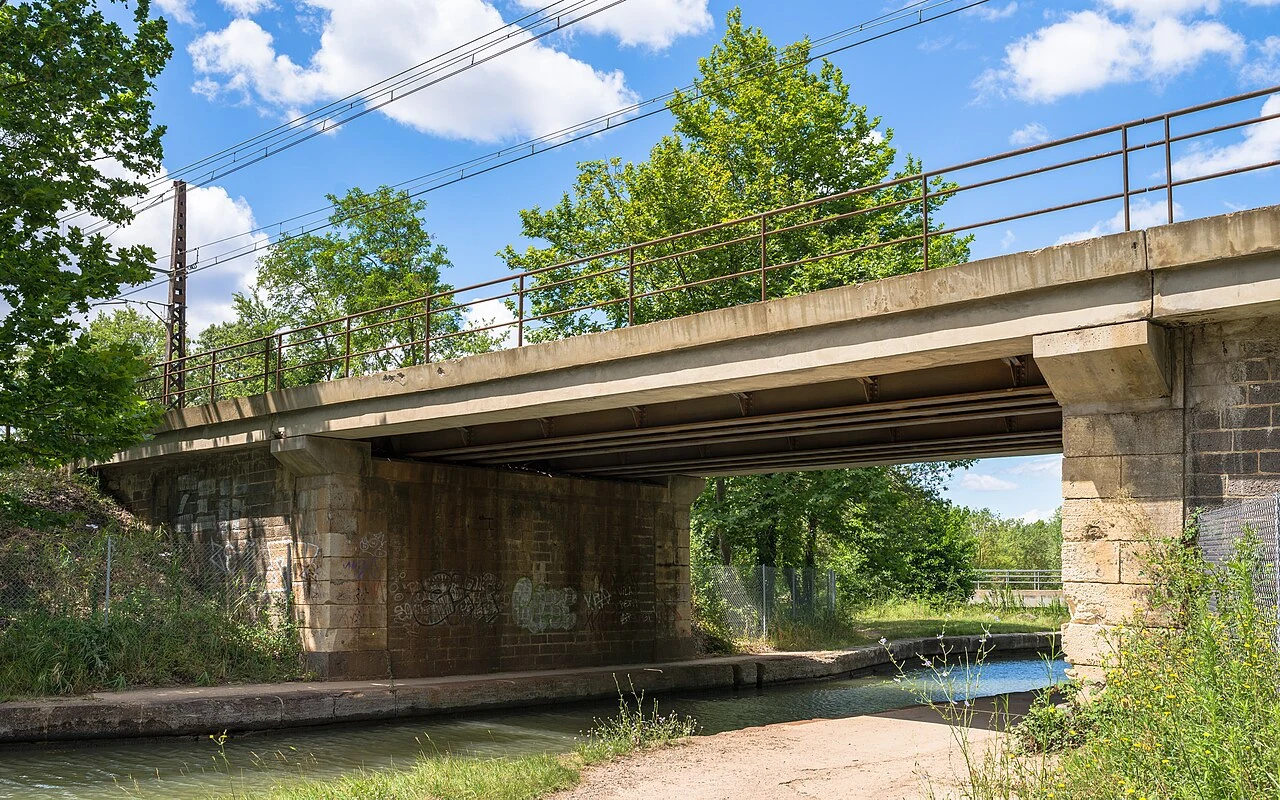
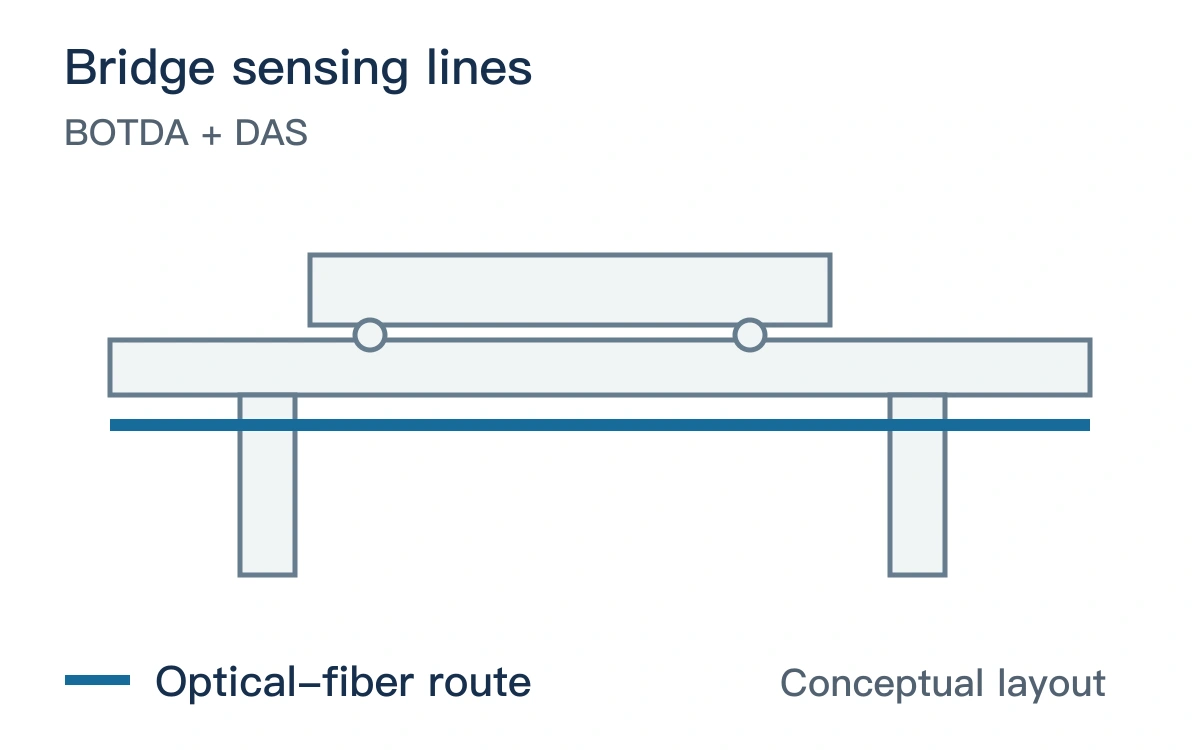
Monitoring task and sensing route
Multiple strain lines need documented cross-sectional geometry, temperature references and joint locations. Displacement reconstruction also requires an explicit structural model and boundary conditions.
Published research observation
Kishida and colleagues used specially installed fibers on a railway bridge for Brillouin static-strain monitoring and DAS measurements of train response. [1]
| Item | Description |
|---|---|
| Study setting | Railway-bridge field observations |
| Research observation | Separate long-term strain and train response |
| Proposed comparison | Map fiber lines to the girder cross-section and expansion joints, with independent temperature records. |
Validation and integration priorities
Align train passages and independent displacement or strain references with the fiber measurements.
Assess static trends, reconstructed displacement and dynamic response separately; retain the model version.
Reference
[1] Kishida K et al. Monitoring a Railway Bridge with Distributed Fiber Optic Sensing Using Specially Installed Fibers. Sensors (Basel, Switzerland) (2025). DOI: 10.3390/s25010098.